The In Salah project in Algeria is an industrial-scale CO2Carbon dioxide storage(CO2Carbon dioxide) A process for retaining captured CO2Carbon dioxide, so that it does not reach the atmosphereThe layer of gases surrounding the earth; the gases are mainly nitrogen (78%) and oxygen (around 21%) project that has been in operation since 2004. CO2Carbon dioxide from several gas fields, which have a CO2Carbon dioxide content of 5-10%, is removed from the production stream to meet the gas export specification of 0.3% CO2Carbon dioxide. Rather than vent the separated CO2Carbon dioxide to atmosphereThe layer of gases surrounding the earth; the gases are mainly nitrogen (78%) and oxygen (around 21%) (as was normal industry practice for such gas plants), joint venture (JV) partners invested an incremental $100 million in a project to compress, dehydrate, transport, and inject about 70% of that CO2Carbon dioxide into a deep saline formationA body of rock of considerable extent with distinctive characteristics that allow geologists to map, describe, and name itUnderground rock where saline water occupies the tiny spaces between the grains of rock down-dip(geology) The steepest angle of descent of a tilted rock strata or feature relative to a horizontal plane of the producing gas horizon. The injectionThe process of using pressure to force fluids down wells formationA body of rock of considerable extent with distinctive characteristics that allow geologists to map, describe, and name it is a 20 m thick Carboniferous sandstoneSand that has turned into a rock due to geological processes, 1900 m below ground with around 15% porosityMeasure for the amount of pore spaceSpace between rock or sediment grains that can contain fluids in a rock and 10 mDA non-SI unit of permeability, milli Darcy, and approximately equal to 1μm2 permeabilityAbility to flow or transmit fluids through a porous solid such as rock (Fig. 3-7). Three state-of-the-art horizontal CO2Carbon dioxide injectionThe process of using pressure to force fluids down wells Wells were drilled perpendicular to the minimum horizontal stress direction, and therefore the dominant fractureAny break in rock along which no significant movement has occurred orientation, to maximise the injectionThe process of using pressure to force fluids down wells capacity. By the end of 2008, over 2.5 million tonnes of CO2Carbon dioxide had been stored underground.
| 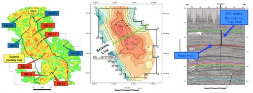
Fig. 3-7: a) Krechba field layout; b) Krechba structure(geology) Geological feature produced by the deformation of the Earth’s crust, such as a fold or a fault(geology) A surface at which strata are no longer continuous, but are found displaced; a feature within a rock such as a fractureAny break in rock along which no significant movement has occurred; or, more generally, the spatial arrangement of rocks map - C10.2; c) 1997 3D seismic image (Mathieson et al., 20112011 - A. Mathieson, J. Midgely, I. Wright, N. Saoula and P. RingroseIn Salah CO2 Storage JIP: CO2 sequestration monitoring and verification technologies applied at Krechba, Algeriasee more). |
The interferometric synthetic aperture radar (InSAR) technique has been used to measure the surface movement caused by CO2Carbon dioxide injectionThe process of using pressure to force fluids down wells in the In Salah CO2Carbon dioxide storage(CO2Carbon dioxide) A process for retaining captured CO2Carbon dioxide, so that it does not reach the atmosphereThe layer of gases surrounding the earth; the gases are mainly nitrogen (78%) and oxygen (around 21%) project (Vasco et al., 20082008 - D. W. Vasco, A. Ferretti and F. VovaliReservoir monitoring and charaterization using satellite geodetic data: interferometric synthetic aperture radar observations from the Krechba fieldsee more). Surface uplift has been detected over all three of the In Salah CO2Carbon dioxide injectionThe process of using pressure to force fluids down wells wells with corresponding subsidence also observed over the gas production area. The distinctive two-lobed uplift pattern over KB- 502 suggests the tensile opening of a structural discontinuity at depth. Shi et al., 20122012 - Ji-Quan Shi, Caglar Sinayuc, Sevket Durucan, Anna KorreAssessment of carbon dioxide plume behaviour within the storage reservoir and the lower caprock around the KB-502 injection well at In Salahsee more conducted a simulation study by history matching the dynamic behaviour of the fault(geology) A surface at which strata are no longer continuous, but are found displaced (zone) transmissibility with the estimated flowing bottom-hole pressure at KB-502. The results are found to be consistent with the stress analysis and the field observations as shown in Fig. 3-7. Specifically, it is believed that, prior to March 2006, the two-lobed surface response is primarily caused by CO2Carbon dioxide injectionThe process of using pressure to force fluids down wells induced tensile reactivation of a non-sealing fault(geology) A surface at which strata are no longer continuous, but are found displaced zone and its subsequent confined growth (lateral propagation and widening) within the C10 formationA body of rock of considerable extent with distinctive characteristics that allow geologists to map, describe, and name it. The increasingly pronounced uplift pattern observed after March 2006, against a steady decline in the FBHP, is predominantly the result of localised CO2Carbon dioxide migrationThe movement of fluids in reservoir rocks into and pressurisation of a fractureAny break in rock along which no significant movement has occurred (or fault(geology) A surface at which strata are no longer continuous, but are found displaced damage) zone in the lower caprockRock of very low permeability that acts as an upper seal to prevent fluid flow out of a reservoir at the top of the tight sandstoneSand that has turned into a rock due to geological processes formationA body of rock of considerable extent with distinctive characteristics that allow geologists to map, describe, and name it (C10.3) overlying the main storage(CO2Carbon dioxide) A process for retaining captured CO2Carbon dioxide, so that it does not reach the atmosphereThe layer of gases surrounding the earth; the gases are mainly nitrogen (78%) and oxygen (around 21%) reservoirA subsurface body of rock with sufficient porosityMeasure for the amount of pore spaceSpace between rock or sediment grains that can contain fluids in a rock and permeabilityAbility to flow or transmit fluids through a porous solid such as rock to store and transmit fluids (C10.2) by the elevated injectionThe process of using pressure to force fluids down wells pressure.
| 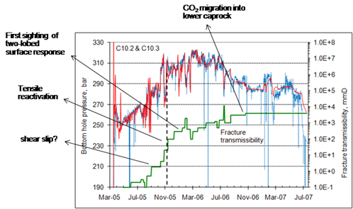
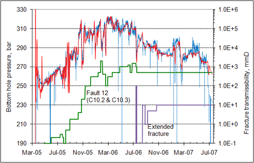
Fig. 3-8: History matching of the JIP field BHP using dynamic fractureAny break in rock along which no significant movement has occurred transmissibility: a) fractureAny break in rock along which no significant movement has occurred growth confined to C10.2 and C10.3; b) implementation of vertical fractureAny break in rock along which no significant movement has occurred extension (Shi et al., 20122012 - Ji-Quan Shi, Caglar Sinayuc, Sevket Durucan, Anna KorreAssessment of carbon dioxide plume behaviour within the storage reservoir and the lower caprock around the KB-502 injection well at In Salahsee more). |