Audigane et al., 2007 presented a 2D reactive transport model of long-term geological storage(CO2) A process for retaining captured CO2, so that it does not reach the atmosphere of carbon dioxide in the Utsira FormationA body of rock of considerable extent with distinctive characteristics that allow geologists to map, describe, and name it in Sleipner. Although their results discussed here were not obtained during the site selection phase, they provide a good impression of what should be anticipated when planning a CO2Carbon dioxide geological storage(CO2) A process for retaining captured CO2, so that it does not reach the atmosphere. Audigane et al., 2007 used the reactive transport code TOUGHREACT and perform a 25 year injectionThe process of using pressure to force fluids down wells scenarioA plausible description of the future based on an internally consistent set of assumptions about key relationships and driving forces; note that scenarios are neither predictions nor forecasts followed by a 10,000 year storage(CO2) A process for retaining captured CO2, so that it does not reach the atmosphere period. They presented detailed information on the different numerical modelling approaches, as wellManmade hole drilled into the earth to produce liquids or gases, or to allow the injection of fluids as a complete reference list dealing with reactive transport modelling. In particular, the numerical method and its implementation in TOUGHREACT are introduced. Details on equations, conditions on the dissolution of CO2Carbon dioxide and kinetics of mineral dissolution and precipitation are wellManmade hole drilled into the earth to produce liquids or gases, or to allow the injection of fluids described.
The site itself, the Sleipner West natural gasGas stored underground; It consists largely of methane, but can also contain other hydrocarbons, water, hydrogen sulphide and carbon dioxide, these other substances are separated before the methane is put into a pipeline or tanker field, is located in the centre of the North Sea. CO2Carbon dioxide is injected into the Utsira FormationA body of rock of considerable extent with distinctive characteristics that allow geologists to map, describe, and name it, which is located above the gas reservoirA subsurface body of rock with sufficient porosity and permeability to store and transmit fluids. The Utsira FormationA body of rock of considerable extent with distinctive characteristics that allow geologists to map, describe, and name it is a large sandy aquiferAn underground layer of fluid-bearing permeable rock or unconsolidated materials (gravel, sand, or silt) with significant permeability to allow flow extending over 26,100 km2 located at a depth from 700 to 1,000 m (Audigane et al., 2007). Details on Utsira FormationA body of rock of considerable extent with distinctive characteristics that allow geologists to map, describe, and name it mineral composition and formationA body of rock of considerable extent with distinctive characteristics that allow geologists to map, describe, and name it waters are described in the paper as wellManmade hole drilled into the earth to produce liquids or gases, or to allow the injection of fluids as comparison between batch geochemical modelling and batch simulations are compared.
Audigane et al., 2007 have approximated the Utsira FormationA body of rock of considerable extent with distinctive characteristics that allow geologists to map, describe, and name it geometry by a vertical 2D mesh with a cylindrical geometrical configuration, centred on an injectionThe process of using pressure to force fluids down wells point located 155 m beneath the top of the 184 m thick formationA body of rock of considerable extent with distinctive characteristics that allow geologists to map, describe, and name it. The mesh contains 22 layers in the vertical direction and 52 in the radial direction. The first cell has a radius of 10 m, and is followed by 20 cells with radial increments increasing in logarithmic progression out to 1 km. Beyond 1 km, 15 cells are present with another logarithmic progression to 3 km. Beyond 3 km, 10 more increments are present with logarithmic progression to a radial distance of 10 km, and finally 5 cells extend out 100 km from the injectionThe process of using pressure to force fluids down wells point; an additional cell with a large volume allows the model to act as an infinite medium (Audigane et al., 2007). Audigane et al., 2007 justify the use of radial mesh geometry by the approximate circular shape of the CO2 plumeDispersing volume of CO2-rich phase contained in target formation observed from seismic surveys.
Hydraulic initial and boundary conditions used in the simulations are shown in Tab. 4-1. Audigane et al., 2007 consider homogeneous sand and shaleClay that has changed into a rock due to geological processes formations, with relative permeabilityAbility to flow or transmit fluids through a porous solid such as rock derived from core measurements. They simulate CO2Carbon dioxide injectionThe process of using pressure to force fluids down wells at a rate of 30 kg/sec for 25 years while accountingActivities aiming to document and report avoided CO2 emissions for a project for an initial pressure of 90 bars at the top of the formationA body of rock of considerable extent with distinctive characteristics that allow geologists to map, describe, and name it.
| Tab. 4-1: HydrogeologicalConcerning water in the geological environment parameters for the 2D model used to simulate CO2Carbon dioxide injectionThe process of using pressure to force fluids down wells at Sleipner with TOUGHREACT (Audigane et al., 2007). 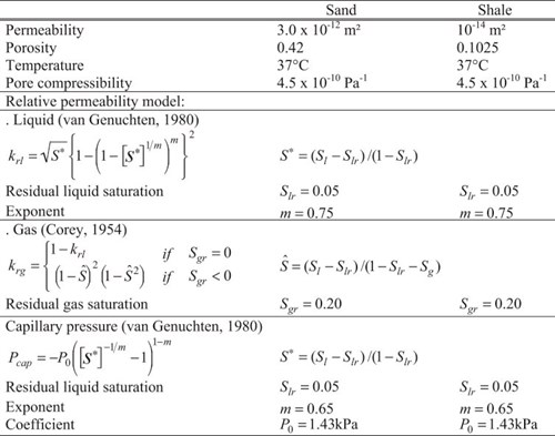
|
Geochemical initial conditions for sand and shaleClay that has changed into a rock due to geological processes mineralogies and for formationA body of rock of considerable extent with distinctive characteristics that allow geologists to map, describe, and name it waters for the 2D model are identical to the batch system considered earlier in Audigane et al., 20062006 - P. Audigane, I. Gaus, I. Czernichowski-Lauriol, K. Pruess and T. XuA long-term 2D vertical modelling of the CO2 storage at Sleipner (North Sea) using TOUGHREACTsee more. A low salinity value of 32 g/l is assumed for the formation waterWater that occurs naturally within the pores of rock formations in both the sand and the shaleClay that has changed into a rock due to geological processes.
The short-term simulations, i.e., 25-year injectionThe process of using pressure to force fluids down wells period, show that the supercritical(CO2) Conditions where carbon dioxide has some characteristics of a gas and some of a liquid CO2 plumeDispersing volume of CO2-rich phase contained in target formation extends laterally about 300 m away from the injectionThe process of using pressure to force fluids down wells point, which is consistent with seismic observations (Audigane et al., 2007). The presence of four intra-shaleClay that has changed into a rock due to geological processes aquifers gives rise to CO2Carbon dioxide accumulations at four different depths and slows the upward CO2Carbon dioxide migrationThe movement of fluids in reservoir rocks. CO2Carbon dioxide dissolution slightly increases brine density and gives rise to a negative (downward) buoyancyTendency of a fluid or solid to rise through a fluid of higher density force. At the end of the 25 year injectionThe process of using pressure to force fluids down wells period, a slight downward migrationThe movement of fluids in reservoir rocks of the brine enriched in CO2Carbon dioxide can be observed. Dissolution of CO2Carbon dioxide makes the brine more acidic and short-term acidification occurs mainly in the area where supercritical(CO2) Conditions where carbon dioxide has some characteristics of a gas and some of a liquid CO2Carbon dioxide is present. Changes in porosityMeasure for the amount of pore space in a rock are minor. For more detailed short-term results, the reader should refer to Audigane et al., 2007.
The long-term simulations, i.e., 10 000 years, show the extent of the CO2 plumeDispersing volume of CO2-rich phase contained in target formation and dissolved CO2Carbon dioxide (Fig. 4-4). The reader should refer to Audigane et al., 2007 for details. At the end of CO2Carbon dioxide injectionThe process of using pressure to force fluids down wells, supercritical(CO2) Conditions where carbon dioxide has some characteristics of a gas and some of a liquid CO2Carbon dioxide migrates quickly upwards, and most of the supercritical(CO2) Conditions where carbon dioxide has some characteristics of a gas and some of a liquid CO2Carbon dioxide accumulates just below the cap rock, except residual CO2Carbon dioxide that is trapped in sediments. The CO2 plumeDispersing volume of CO2-rich phase contained in target formation extends to a maximum radius of 2,000 m around the injectionThe process of using pressure to force fluids down wells point. CO2Carbon dioxide starts to dissolve in the brine, and the free gas is completely dissolved after 6,000 years. The brine containing dissolved CO2Carbon dioxide tends to migrate downward as it is approximately 10 kg/m3 denser than brine without CO2Carbon dioxide. Molecular diffusion from the gas plume to the brine induces a hydrodynamically unstable layering leading to the development of convective currents in the formationA body of rock of considerable extent with distinctive characteristics that allow geologists to map, describe, and name it. The brine containing dissolved CO2Carbon dioxide is carried downward and is progressively replaced by brine with less CO2Carbon dioxide. Streamlines of fluid migrationThe movement of fluids in reservoir rocks showing convective cells are represented in Fig. 4-4 after 2,000 years of simulation. The slow brine convection accelerates CO2Carbon dioxide dissolution. After 10,000 years, a large volume near the bottom of the formationA body of rock of considerable extent with distinctive characteristics that allow geologists to map, describe, and name it contains brine with dissolved CO2Carbon dioxide out to a radius of 4,000 m.
Key results of Audigane et al., 2007 are the following:
-
The role of convective mixing is crucial for long term CO2Carbon dioxide dissolution;
-
The process of gas dissolution and subsequent buoyant convection and mixing of brine involves a range of spatial scales;
-
The interaction between flow and geochemical reactions and its impact on the overall reactivity can be accurately assessed only through coupled modelling and;
-
For long-term reactivity, the evolution of the acidity is crucial; it is directly linked to the amount of CO2Carbon dioxide dissolved in the brine.
Audigane et al., 2007 identified four main types of geochemical interactions:
- Calcite dissolution and precipitation;
-
Albite alteration;
- Muscovite alteration.
The assessment of the amount of CO2Carbon dioxide stored and the induced porosityMeasure for the amount of pore space in a rock changes are presented as a mass balance of carbon dioxide in mineral, supercritical(CO2) Conditions where carbon dioxide has some characteristics of a gas and some of a liquid and aqueous phases (Fig. 4-5). Mineral tTrapping obviously plays a minor role, although it increases slowly with time and therefore contributes to long-term stability of the storage(CO2) A process for retaining captured CO2, so that it does not reach the atmosphere process. Regarding the spatial distribution of CO2Carbon dioxide stored in minerals, the simulated mineral storage(CO2) A process for retaining captured CO2, so that it does not reach the atmosphere occurs mainly at the top of the reservoirA subsurface body of rock with sufficient porosity and permeability to store and transmit fluids and in the major downward convection zone above the injectionThe process of using pressure to force fluids down wells point. The induced porosityMeasure for the amount of pore space in a rock changes are minor: a decrease of less than 2.5 % in the sands, and an increase of up to 15 % in the shales (Fig. 4-6). Audigane et al., 2007 point out that the difference in the porosityMeasure for the amount of pore space in a rock changes between sands and shales illustrate the importance of coupled transport and chemical reaction modelling: in the shales the porosityMeasure for the amount of pore space in a rock change is the inverse of what was seen in the batch modelling (Audigane et al., 2007).
| 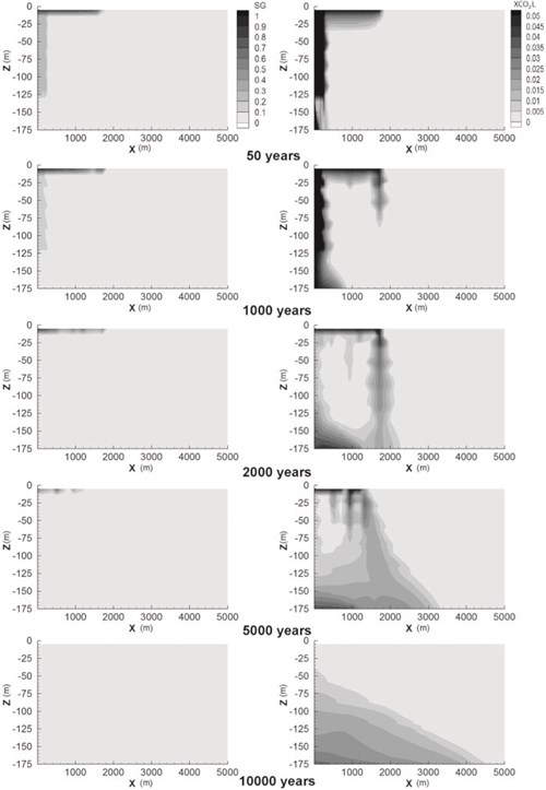
Fig. 4-4: Supercritical(CO2Carbon dioxide) Conditions where carbon dioxide has some characteristics of a gas and some of a liquid CO2Carbon dioxide gas phase (SG) migrationThe movement of fluids in reservoir rocks and mass fraction of the dissolved CO2Carbon dioxide in the brine (XCO2L) simulated from 50 years after injectionThe process of using pressure to force fluids down wells until 10 000 years (Audigane et al.,. 2007). |
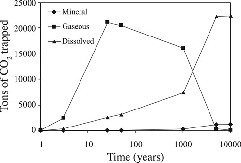 Fig. 4-5: Total amounts of carbon dioxide present as a free (supercritical(CO2Carbon dioxide) Conditions where carbon dioxide has some characteristics of a gas and some of a liquid) gas phase, dissolved in the aqueous phase, and sequestered in minerals (Audigane et al., 2007) |
| 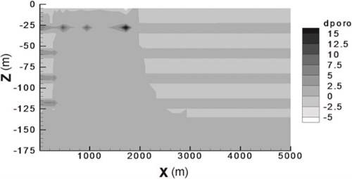
Fig. 4-6: PorosityMeasure for the amount of pore spaceSpace between rock or sediment grains that can contain fluids in a rock changes after 10,000 years of simulation (Audigane et al., 2007). |
Audigane et al., 2007 conclude that the geochemical reactivity of the Utsira FormationA body of rock of considerable extent with distinctive characteristics that allow geologists to map, describe, and name it is rather low, so that mineral trapping(CO2) Containment or immobilisation of CO2, there are four main trapping mechanisms: structural or stratigraphic trapping; residual CO2 trapping (capillary trapping) by capillary forces; solubility trapping by dissolution of CO2 in resident formation fluids forming a non-buoyant fluid; and mineral trapping where CO2 is absorbed by solid minerals present in the storage volume makes only minor contributions to CO2Carbon dioxide storage(CO2) A process for retaining captured CO2, so that it does not reach the atmosphere. Solubility is the dominant long-term storage(CO2) A process for retaining captured CO2, so that it does not reach the atmosphere mechanism, which appears to be essentially complete after 5 000 years. Physical and chemical heterogeneity play important roles in the geochemical evolution and associated changes in porosityMeasure for the amount of pore space in a rock. The Audigane et al., 2007 results suggest that the Utsira sand is unlikely to undergo major chemical changes due to CO2Carbon dioxide injectionThe process of using pressure to force fluids down wells. Anticipated porosityMeasure for the amount of pore space in a rock changes are relatively minor, with a slight long-term decrease expected in the sands and a more significant increase in the shales. Density differences between brines with different dissolved CO2Carbon dioxide concentrations give rise to convective flows that cross the shaleClay that has changed into a rock due to geological processes layers, mobilizing species that subsequently promote precipitation further downstream. Processes in which dissolution of minerals occurs in one region while precipitation occurs in another region with different mineralogy can only be analysed and modelled by coupling flow and transport with chemical reactions. The strong interplay between multiphase and density dependent flows with rock-fluid interactions makes it difficult to interpret modelled results in terms of a few dominant reactions. Separate batch geochemical modelling provides useful guidance for interpretation, but Audigane et al., 2007 show that in some cases the coupling to transport can give rise to qualitatively different behaviour to that derived from batch models.