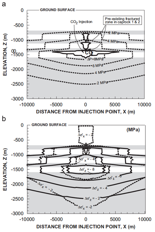
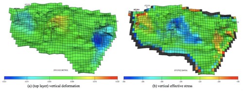
Rutqvist et al., 20082008 - J. Rutqvist, J. T. Birkholzer, Chin-Fu TsangCoupled reservoir–geomechanical analysis of the potential for tensile and shear failure associated with CO2 injection in multilayered reservoir–caprock systemssee more modelled multi-layer systems using a coupling between TOUGH2 and FLAC3D. In this study, CO2Carbon dioxide is injected as supercritical(CO2) Conditions where carbon dioxide has some characteristics of a gas and some of a liquid fluid for 30 years. It spreads both laterally and upward, displacing the native brine. During the injectionThe process of using pressure to force fluids down wells period, the reservoirA subsurface body of rock with sufficient porosity and permeability to store and transmit fluids pressure increases gradually but stays below the lithostatic stress at the depth of the injectionThe process of using pressure to force fluids down wells zone. The poro-elastic modelling showed that the effective stress decreases as fluid pressure increases within the CO2Carbon dioxide storage(CO2) A process for retaining captured CO2, so that it does not reach the atmosphere system, as shown in Fig. 5-1. Le Gallo et al., 20062006 - Y. Le Gallo, L. Trenty, A. Michel, S. Vidal-Gilbert, T. Parra and L. JeanninLong-term flow simulations of CO2 storage in saline aquifersee more presented the long-term impact of CO2Carbon dioxide injectionThe process of using pressure to force fluids down wells into a saline aquiferAn underground layer of fluid-bearing permeable rock or unconsolidated materials (gravel, sand, or silt) with significant permeability to allow flow using the reactive transport model COORES and the geomechanical model ABAQUS. Shi and Durucan, 20092009 - J.-Q. Shi and S. DurucanA coupled reservoir-geomechanical simulation study of CO2 storage in a nearly depleted natural gas reservoirsee more performed a coupled geomechanical-reservoirA subsurface body of rock with sufficient porosity and permeability to store and transmit fluids modelling study using Schlumberger's ECLIPSE 300 simulator. The aim of the study was to evaluate the hydro-mechanical response of the reservoirA subsurface body of rock with sufficient porosity and permeability to store and transmit fluids rock and overburdenRocks and sediments above any particular stratum formations to historical and current gas production rates and several CO2Carbon dioxide injectionThe process of using pressure to force fluids down wells scenarios at Atzbach-Schwanenstadt natural gasGas stored underground; It consists largely of methane, but can also contain other hydrocarbons, water, hydrogen sulphide and carbon dioxide, these other substances are separated before the methane is put into a pipeline or tanker field. The simulation results in terms of the vertical deformation at the top of the reservoirA subsurface body of rock with sufficient porosity and permeability to store and transmit fluids and changes in the vertical effective stress after 40 years CO2Carbon dioxide injectionThe process of using pressure to force fluids down wells are presented in Fig. 5-2.
| 
Fig. 5-1: Simulated coupled reservoirA subsurface body of rock with sufficient porosityMeasure for the amount of pore spaceSpace between rock or sediment grains that can contain fluids in a rock and permeabilityAbility to flow or transmit fluids through a porous solid such as rock to store and transmit fluids-geomechanical responses after 30 years of CO2Carbon dioxide-injectionThe process of using pressure to force fluids down wells into a multi-layered and Faulted system: a) spread of CO2Carbon dioxide rich fluid (solid-line contours) and changes in fluid pressure (dashed-line contours); b) fluid-pressure induced changes in vertical (solid-line contours) and horizontal (dashed-line contours) effective stresses (Rutqvist et al., 20082008 - J. Rutqvist, J. T. Birkholzer, Chin-Fu TsangCoupled reservoir–geomechanical analysis of the potential for tensile and shear failure associated with CO2 injection in multilayered reservoir–caprock systemssee more). |
| 
Fig. 5-2: Simulated distribution of vertical deformation and effective vertical stress at 2050 (Shi et al., 2009). |