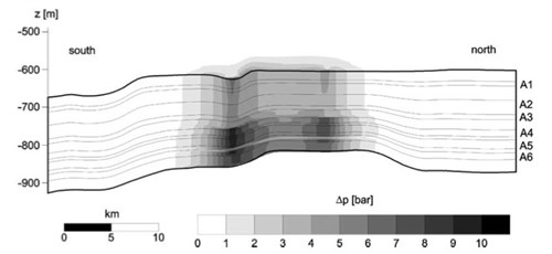
Comerlati et al., 20062006 - A. Comerlati, M. Ferronato, G. Gambolati, M. Putti and P. TeatiniFluid-Dynamic and Geomechanical Effects of CO2 Sequestration below the Venice Lagoonsee more investigated the potential of CO2Carbon dioxide injectionThe process of using pressure to force fluids down wells below the Venice Lagoon using available geological, geophysical, hydrologic, and geomechanical data, and with the aid of advanced numerical models. Using a coupled flow-geomechanical model, the amount of the rise of the ground surface because of the reductionThe gain of one or more electrons by an atom, molecule, or ion of the effective stress in the aquiferAn underground layer of fluid-bearing permeable rock or unconsolidated materials (gravel, sand, or silt) with significant permeability to allow flow and consequent rock expansion could be estimated. A seven cm uplift has been obtained with the most probable parameter selection (base case) (Fig. 5-3).
| 
Fig. 5-3: Base case predicted overpressurePressure created in a reservoir that exceeds the pressure inherent at the reservoir depth along the north-south cross-section of Venice Lagoon at the end of a 10 year simulation period (Comerlati et al., 20062006 - A. Comerlati, M. Ferronato, G. Gambolati, M. Putti and P. TeatiniFluid-Dynamic and Geomechanical Effects of CO2 Sequestration below the Venice Lagoonsee more). |
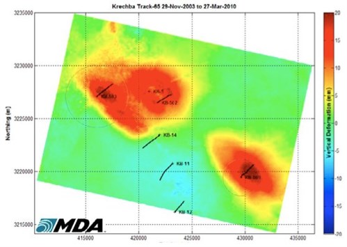
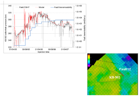
Another area where the surface uplift caused by the injectionThe process of using pressure to force fluids down wells of CO2Carbon dioxide has been studied is the In Salah gas field in Algeria. Using the surface deformation detected by Interferometric Synthetic Aperture Radar (InSAR) around three different injectionThe process of using pressure to force fluids down wells wells (KB501, KB502 and KB503), methods that provide early warnings about potential leakage(in CO2 storage) The escape of injected fluid from the storage formation to the atmosphere or water column of CO2Carbon dioxide from the reservoirA subsurface body of rock with sufficient porosity and permeability to store and transmit fluids and the possibility of monitoringMeasurement and surveillance activities necessary for ensuring safe and reliable operation of a CGS project (storage integrity), and for estimating emission reductions the injectionThe process of using pressure to force fluids down wells performance have been tested. The InSAR data show a surface uplift of the order of 5 mm per year above active CO2Carbon dioxide injectionThe process of using pressure to force fluids down wells wells and the uplift pattern extends several km from the injectionThe process of using pressure to force fluids down wells wells (Onuma and Ohkawa, 20092009 - T. Onuma and S. OhkawaDetection of surface deformation related with CO2 injection by DInSAR at In Salah, Algeriasee more; Vasco et al., 20082008 - D. W. Vasco, A. Ferretti and F. VovaliReservoir monitoring and charaterization using satellite geodetic data: interferometric synthetic aperture radar observations from the Krechba fieldsee more). The surface heave pattern of NW-SE trending elongation suggests a relationship between structural features and the distribution of the CO2 plumeDispersing volume of CO2-rich phase contained in target formation. Onuma and Ohkawa, 20092009 - T. Onuma and S. OhkawaDetection of surface deformation related with CO2 injection by DInSAR at In Salah, Algeriasee more concluded that when an adequate number of interferometry pairs are available, the deformation time series can be detected, which may be supplemental data for refining the model of underground distribution of injected CO2Carbon dioxide. The InSAR data was used by Rutqvist et al., (2009) to constrain the coupled reservoirA subsurface body of rock with sufficient porosity and permeability to store and transmit fluids-geomechanical model. The uplift depends on the magnitude of pressure change, injectionThe process of using pressure to force fluids down wells volume and elastic properties of the reservoirA subsurface body of rock with sufficient porosity and permeability to store and transmit fluids and overburdenRocks and sediments above any particular stratum. The sensitivity studies showed that although most of the observed uplift magnitude can be explained by poro-elastic expansion of the 20 m thick injectionThe process of using pressure to force fluids down wells zone, there could also be a significant contribution from pressure changes within the adjacent caprockRock of very low permeability that acts as an upper seal to prevent fluid flow out of a reservoir. Using small-scale faults and fractures, an integrated geomechanical model, which includes the Carboniferous (C10.2) injectionThe process of using pressure to force fluids down wells zone, the caprockRock of very low permeability that acts as an upper seal to prevent fluid flow out of a reservoir overburdenRocks and sediments above any particular stratum and underburden was constructed by Gemmer et al., 2012 in order to predict the fluid flow and rock mechanical response to pore pressure changes. The stress and strain resulting from the injectionThe process of using pressure to force fluids down wells of CO2Carbon dioxide is simulated with ABAQUS software using a two-dimensional plane-strain finite element model (Fig. 5-4). Pressure/fluid-flow in fractures seen in the seismic interpretation that is indicated by seismic time-shifts is validated by the estimated stress change through the geomechanical model. The observed 2 cm of uplift could only be explained by an unrealistically low stiffness. Therefore, Gemmer et al., 2012 studied the effects of the rock mechanical properties on the surface displacement pattern by a number of sensitivity models. The distinct uplift of the ground surface observed directly above the fault(geology) A surface at which strata are no longer continuous, but are found displaced/fractureAny break in rock along which no significant movement has occurred zone at the KB-502 location (Fig. 5-5) could be explained by cases where pre-existing faulting and fracturing has led to material weakening due to reductionThe gain of one or more electrons by an atom, molecule, or ion of the cohesion or reductionThe gain of one or more electrons by an atom, molecule, or ion of the minimum horizontal stress.
| 
Fig. 5-4: Satellite image of cumulative surface deformation at Krechba due to CO2Carbon dioxide injectionThe process of using pressure to force fluids down wells (Mathieson et al., 20112011 - A. Mathieson, J. Midgely, I. Wright, N. Saoula and P. RingroseIn Salah CO2 Storage JIP: CO2 sequestration monitoring and verification technologies applied at Krechba, Algeriasee more). |
| 
Fig. 5-5: a) History matching of the CO2Carbon dioxide injectionThe process of using pressure to force fluids down wells pressure at In Salah at injectionThe process of using pressure to force fluids down wells wellManmade hole drilled into the earth to produce liquids or gases, or to allow the injectionThe process of using pressure to force fluids down wells of fluids KB-502 b) implementation of the fault(geology) A surface at which strata are no longer continuous, but are found displaced zone COntained in C10.2-3 in the reservoirA subsurface body of rock with sufficient porosityMeasure for the amount of pore spaceSpace between rock or sediment grains that can contain fluids in a rock and permeabilityAbility to flow or transmit fluids through a porous solid such as rock to store and transmit fluids model (Shi et al., 2013). |