Many of the ongoing riskConcept that denotes the product of the probability of a hazard and the subsequent consequence of the associated event efforts are now cooperating to identify, classify and screen all factors that may influence the safety of storage(CO2Carbon dioxide) A process for retaining captured CO2Carbon dioxide, so that it does not reach the atmosphereThe layer of gases surrounding the earth; the gases are mainly nitrogen (78%) and oxygen (around 21%) facilities, by using the Features, Events and Processes (FEP) methodology (IPCCIntergovernmental Panel on Climate Change, 2005). RiskConcept that denotes the product of the probability of a hazard and the subsequent consequence of the associated event identification (or qualification) of hazards includes estimation of the probability of specific features, events, and processes (FEPs) that could contribute to, or prevent, unplanned CO2Carbon dioxide migrationThe movement of fluids in reservoir rocks from the confining zone (NETL, 20112011 - NETLRisk Analysis and Simulation for Geologic Storage of CO2, Version 1.0see more; DNV, 20102010 - DNVCO2QUALSTORE - Guideline for selection and qualification of sites and projects for geological storage of CO2see more):
-
Features include the physical characteristics or properties of the system, such as lithologyThe nature and composition of rocks, porosityMeasure for the amount of pore spaceSpace between rock or sediment grains that can contain fluids in a rock, permeabilityAbility to flow or transmit fluids through a porous solid such as rock, caprockRock of very low permeability that acts as an upper seal to prevent fluid flow out of a reservoir thickness, faults, wells, leaky wellbores and nearby communities.
-
Events include discrete occurrences that may occur in the future affecting one or more components of the system, such as earthquakes, subsidence, drilling, penetration of the storage(CO2Carbon dioxide) A process for retaining captured CO2Carbon dioxide, so that it does not reach the atmosphereThe layer of gases surrounding the earth; the gases are mainly nitrogen (78%) and oxygen (around 21%) site by new wells, injectionThe process of using pressure to force fluids down wells pressure increases, borehole casingA pipe which is inserted to stabilise the borehole of a well after it is drilled leak, pipe fractureAny break in rock along which no significant movement has occurred and wellManmade hole drilled into the earth to produce liquids or gases, or to allow the injectionThe process of using pressure to force fluids down wells of fluids blow-outs.
-
Processes include physico-chemical processes, often marked by gradual or continuous changes, that influence the evolution of the system; chemical reactions, precipitation of minerals, ground water flow, multiphase flow, CO2Carbon dioxide phase behaviour, gravity-driven CO2Carbon dioxide movement or residual saturationThe fraction of the injected CO2Carbon dioxide that is trapped in pores by capillary forces trapping(CO2Carbon dioxide) ContainmentRestriction of the movement of a fluid to a designated volume (e.g. reservoir) or immobilisation of CO2Carbon dioxide, there are four main trapping mechanisms: structural or stratigraphicThe order and relative position of geological strata trapping; residual CO2Carbon dioxide trapping (capillary trappingImmobilisation of a fraction of in-situ fluids by capillary forces) by capillary forces; solubility trappingA process in which fluids are retained by dissolution in liquids naturally present by dissolution of CO2Carbon dioxide in resident formationA body of rock of considerable extent with distinctive characteristics that allow geologists to map, describe, and name it fluids forming a non-buoyant fluid; and mineral trapping where CO2Carbon dioxide is absorbed by solid minerals present in the storage(CO2Carbon dioxide) A process for retaining captured CO2Carbon dioxide, so that it does not reach the atmosphereThe layer of gases surrounding the earth; the gases are mainly nitrogen (78%) and oxygen (around 21%) volume, geomechanical stress changes and corrosion of borehole casingA pipe which is inserted to stabilise the borehole of a well after it is drilled.
Fig. 6-6 illustrates the relationship between, features, events and processes (FEP) and potential riskConcept that denotes the product of the probability of a hazard and the subsequent consequence of the associated event impacts. For example, the storage(CO2Carbon dioxide) A process for retaining captured CO2Carbon dioxide, so that it does not reach the atmosphereThe layer of gases surrounding the earth; the gases are mainly nitrogen (78%) and oxygen (around 21%) reservoirA subsurface body of rock with sufficient porosityMeasure for the amount of pore spaceSpace between rock or sediment grains that can contain fluids in a rock and permeabilityAbility to flow or transmit fluids through a porous solid such as rock to store and transmit fluids may have insufficient capacity or injectivityA measure of the rate at which a quantity of fluid can be injected into a well, leading to the riskConcept that denotes the product of the probability of a hazard and the subsequent consequence of the associated event that CO2Carbon dioxide injectionThe process of using pressure to force fluids down wells cannot be sustained over the life of the project. The impact assessment would estimate the techno-economic and societal impacts of such a scenarioA plausible description of the future based on an internally consistent set of assumptions about key relationships and driving forces; note that scenarios are neither predictions nor forecasts (NETL, 20112011 - NETLRisk Analysis and Simulation for Geologic Storage of CO2, Version 1.0see more).
| 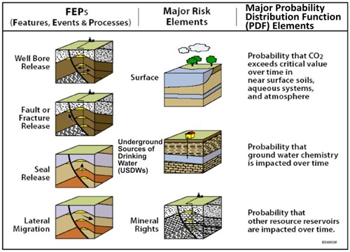
Fig. 6-6: Examples of relationships among Features, Events, Processes, and Potential Impacts (NETL, 20112011 - NETLRisk Analysis and Simulation for Geologic Storage of CO2, Version 1.0see more). |
The riskConcept that denotes the product of the probability of a hazard and the subsequent consequence of the associated event is based on simulations of different scenarios built up from FEPs. Main steps in the assessment are: (a) establishing riskConcept that denotes the product of the probability of a hazard and the subsequent consequence of the associated event criteria, (b) description of the geological system by investigation and screening of all features,events and processes (FEPs) that are relevant to the long-term safety, so called FEP analysis, (c) identification of the most important FEPs, (d) scenarioA plausible description of the future based on an internally consistent set of assumptions about key relationships and driving forces; note that scenarios are neither predictions nor forecasts selection and analysis based on the FEP analysis, (e) system model development using numerical reservoirA subsurface body of rock with sufficient porosity and permeability to store and transmit fluids simulation, and (f) qualitative and quantitative consequence analysis (NETL, 20112011 - NETLRisk Analysis and Simulation for Geologic Storage of CO2, Version 1.0see more; Chadwick et al., 2008).The very first step of riskConcept that denotes the product of the probability of a hazard and the subsequent consequence of the associated event is the definition of the assessment basis, which consists of: (a) riskConcept that denotes the product of the probability of a hazard and the subsequent consequence of the associated event acceptance criteria, (b) containmentRestriction of the movement of a fluid to a designated volume (e.g. reservoir) concept and (c) setting of the storage(CO2Carbon dioxide) A process for retaining captured CO2Carbon dioxide, so that it does not reach the atmosphereThe layer of gases surrounding the earth; the gases are mainly nitrogen (78%) and oxygen (around 21%) site.
In some cases, for the assessment of a storage(CO2) A process for retaining captured CO2, so that it does not reach the atmosphere structure(geology) Geological feature produced by the deformation of the Earth’s crust, such as a fold or a fault; a feature within a rock such as a fracture; or, more generally, the spatial arrangement of rocks, a modified performance assessment (PA) methodology can be used. PA is a system analysis that predicts the behaviour or "performance" of an element of a geological storage(CO2) A process for retaining captured CO2, so that it does not reach the atmosphere project (specified system) relative to one or more performance standards (system performance indicators). If the indicator is a health, safety and environmental (HSEHealth, safety and environment) effect, the PA is termed a safety assessment.
The FEP analysis is performed using databases developed in earlier CO2Carbon dioxide safety assessment studies (Wildenborg et al., 2005; Maul and Savage, 20042004 - P. Maul and D. SavageThe IEA Weyburn CO2 Monitoring and Storage Project: Assessment of Long-term Performance and Safetysee more). The databases are used as selection tools for early screening of relevant FEPs. The main steps in the FEP analysis are illustrated in Fig. 6-7. The main tools that support the process are the FEP database and the visual analyser (Chadwick et al., 2008). A distinction can be made between features as static factors, and events and processes (EPs) as dynamic factors. For each individual EP the following aspects can be evaluated: (i) specifications of how the EP is interpreted, e.g. its relation to safety, (ii) semi-quantitative probability that an EP will occur, and (iii) potential impact if the EP occurs. EP grouping can be carried out and criteria for EP groups can be based on the information that is available in the FEP database (Wildenborg et al., 2005), such as: (i) common parameters (distinct features such as permeabilityAbility to flow or transmit fluids through a porous solid such as rock, rock strength, etc), (ii) process types (mechanical, chemical, thermal, hydraulic, biological), (iii) effect type (on matrix, fluid, stored CO2Carbon dioxide, indirect), (iv) timescale of EP occurrence (in 100 years, in 1000 years or in 10000 years), (v) duration scale of EP while occurring (hours, days, centuries and longer), and (vi) spatial scale (metres, km, tens of km, basinA geological region with sedimentary strata dipping towards a common axis or centre scale) (Chadwick et al., 2008).
| 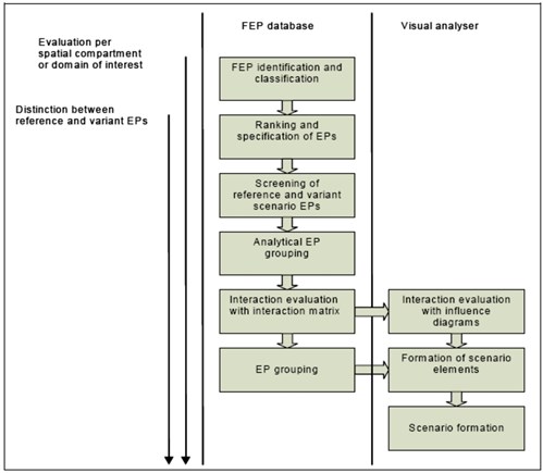
Fig. 6-7: Main steps in used FEP analysis methodology. Based on the analysis process in Wildenborg et al., 2005 and Chadwick et al., 2008. |
The FEP database holds FEPs that may have a potential effect on the safety of the storage(CO2) A process for retaining captured CO2, so that it does not reach the atmosphere system (Chadwick et al., 2008). It can help the site-specific description of the system and identification of site-specific issues, allowing comprehensive evaluation of each site's unique characteristics (CSLF, 20092009 - CSLFPhase I Final Report from CSLF Risk Assessment Task Forcesee more). FEP database also ties information on individual FEPs to relevant literature and allow classification with respect to likelihood, spatial scale, time scale and so on. However, there are alternative approaches (IPCCIntergovernmental Panel on Climate Change, 2005). All FEPs in the database have a complete set of identification and classification attributes (Fig. 6-8). These attributes have been assigned generically, and could be used to filter case-specific FEPs with respect to the assessment basis (Chadwick et al., 2008).
Detailed lists of FEPs for geologic systems have evolved for various environmental needs, and these have been adapted to a generic database for geologic storage(CO2) A process for retaining captured CO2, so that it does not reach the atmosphere of CO2Carbon dioxide by Quintessa (Savage et al., 20042004 - D. Savage, P. R. Maul, S. Benbow and R. C. WalkeA generic FEP database for the assessment of long term performance and safety of the geological storage of CO2see more; Maul et al., 20052005 - P. R. Maul, D. Savage, S. J. Benbow, R. C. Walke and R. BruinDevelopment of a FEP database for the geological storage of carbon dioxidesee more). The Quintessa database (http://www.quintessa-online.com/fep.php) currently includes around 200 FEPs in a hierarchical structure(geology) Geological feature produced by the deformation of the Earth’s crust, such as a fold or a fault; a feature within a rock such as a fracture; or, more generally, the spatial arrangement of rocks, with individual FEPs grouped into eight categories. Each FEP has a text description and an associated discussion of its relevance to long-term performance and safety. Key references from the published literature are included to enable retrieval of more detailed information for each FEP. The database incorporates hyperlinks to other relevant sources of information (reports, websites, maps, photographs, videos, etc.), and is searchable in a variety of ways. The generic FEP database is intended to be the first stage in developing a FEP-based auditing capability for more detailed project-specific FEP databases. At present there are no project specific FEP databases in the system, but the capability is present and it is hoped that some project-specific databases will be added in the near future.
| 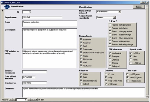
Fig. 6-8: FEP Example of generic FEP attributes in the FEP database (Chadwick et al., 2008). |
Utilising the definition of the storage(CO2) A process for retaining captured CO2, so that it does not reach the atmosphere system set out in the assessment basis, the FEPs are ranked and screened in order to identify the FEPs that are likely or very likely to occur. These FEPs are grouped and assigned to specific zones within the geological storage(CO2) A process for retaining captured CO2, so that it does not reach the atmosphere system (compartments). Because the future evolution of a geologic system cannot be precisely determined, various possible Scenarios for possible evolutions of the system and situations of particular interest are developed (NETL, 20112011 - NETLRisk Analysis and Simulation for Geologic Storage of CO2, Version 1.0see more). Most RiskConcept that denotes the product of the probability of a hazard and the subsequent consequence of the associated event assessments involve the use of scenarios that describe possible future states of the storage(CO2) A process for retaining captured CO2, so that it does not reach the atmosphere facility and events that result in leakage(in CO2 storage) The escape of injected fluid from the storage formation to the atmosphere or water column of CO2Carbon dioxide or other risks. Each scenarioA plausible description of the future based on an internally consistent set of assumptions about key relationships and driving forces; note that scenarios are neither predictions nor forecasts may be considered as an assemblage of selected FEPs (IPCCIntergovernmental Panel on Climate Change, 2005). Some rRisk assessments define a reference scenarioA plausible description of the future based on an internally consistent set of assumptions about key relationships and driving forces; note that scenarios are neither predictions nor forecasts that represents the most probable evolution of the system. Variant scenarios are then constructed with alternative FEPs. Various methods are used to structure(geology) Geological feature produced by the deformation of the Earth’s crust, such as a fold or a fault; a feature within a rock such as a fracture; or, more generally, the spatial arrangement of rocks and rationalize the process of scenarioA plausible description of the future based on an internally consistent set of assumptions about key relationships and driving forces; note that scenarios are neither predictions nor forecasts definition in an attempt to reduce the role of subjective judgements in determining the outcomes (IPCCIntergovernmental Panel on Climate Change, 2005). For example, based on the FEP analysis and the scenarioA plausible description of the future based on an internally consistent set of assumptions about key relationships and driving forces; note that scenarios are neither predictions nor forecasts formationA body of rock of considerable extent with distinctive characteristics that allow geologists to map, describe, and name it, some "what if?" scenarios can be identified for simulation: (i) reference scenarioA plausible description of the future based on an internally consistent set of assumptions about key relationships and driving forces; note that scenarios are neither predictions nor forecasts assuming that no failure of the containmentRestriction of the movement of a fluid to a designated volume (e.g. reservoir) zone occurs, (ii) leaking sealAn impermeable rock that forms a barrier above and around a reservoir such that fluids are held in the reservoir scenarioA plausible description of the future based on an internally consistent set of assumptions about key relationships and driving forces; note that scenarios are neither predictions nor forecasts assuming that the sealAn impermeable rock that forms a barrier above and around a reservoir such that fluids are held in the reservoir will fail by geochemical processes, whereby CO2Carbon dioxide enhances the permeabilityAbility to flow or transmit fluids through a porous solid such as rock of the caprockRock of very low permeability that acts as an upper seal to prevent fluid flow out of a reservoir and migrates into the overburdenRocks and sediments above any particular stratum. (iii) leaking wellManmade hole drilled into the earth to produce liquids or gases, or to allow the injection of fluids scenarioA plausible description of the future based on an internally consistent set of assumptions about key relationships and driving forces; note that scenarios are neither predictions nor forecasts assuming that the sealing capacity of an existing old wellManmade hole drilled into the earth to produce liquids or gases, or to allow the injection of fluids will fail, followed by transport of CO2Carbon dioxide along the wellManmade hole drilled into the earth to produce liquids or gases, or to allow the injection of fluids trajectory, (iv) leaking fault(geology) A surface at which strata are no longer continuous, but are found displaced scenarioA plausible description of the future based on an internally consistent set of assumptions about key relationships and driving forces; note that scenarios are neither predictions nor forecasts assuming that there is a fault(geology) A surface at which strata are no longer continuous, but are found displaced through the caprockRock of very low permeability that acts as an upper seal to prevent fluid flow out of a reservoir, and that the sealing capacity of the fault(geology) A surface at which strata are no longer continuous, but are found displaced will fail, followed by CO2Carbon dioxide escape from the containmentRestriction of the movement of a fluid to a designated volume (e.g. reservoir) zone along the fault(geology) A surface at which strata are no longer continuous, but are found displaced (Chadwick et al., 2008). The data input to early stage riskConcept that denotes the product of the probability of a hazard and the subsequent consequence of the associated event will frequently be associated with significant uncertainty. Consequently, early stage riskConcept that denotes the product of the probability of a hazard and the subsequent consequence of the associated event may be qualitative, based on FEPs, to lead to site selection or data characterization. It should be refined over time to incorporate new data, and at least at the closure of a project a minimal confidence should be gained to proceed with transfer of responsibilityTransfer of all rights and obligations associated with a storage site to a designated authority; will normally be granted when the obligations in the site closure permit has been met with an adequate level of confidence. Such analyses are typically based on expert elicitation activities, implying that the results to some extent depend on the subjective views and opinions of the experts involved. A key challenge is therefore how to enhance repeatability and consistency of riskConcept that denotes the product of the probability of a hazard and the subsequent consequence of the associated event assessments to make the associated process and results verifiable and auditable (DNV, 20102010 - DNVCO2QUALSTORE - Guideline for selection and qualification of sites and projects for geological storage of CO2see more).
The FEP assessment methodology is useful but still has gaps in knowledge. This concerns many aspects, e.g. safety and riskConcept that denotes the product of the probability of a hazard and the subsequent consequence of the associated event terminology, usage of FEP database, scenarioA plausible description of the future based on an internally consistent set of assumptions about key relationships and driving forces; note that scenarios are neither predictions nor forecasts evaluation, assessment criteria, modelling tools and so on (Chadwick et al., 2008). Figure 6.9 shows different stages in a FEP analysis, from identification to scenarioA plausible description of the future based on an internally consistent set of assumptions about key relationships and driving forces; note that scenarios are neither predictions nor forecasts formationA body of rock of considerable extent with distinctive characteristics that allow geologists to map, describe, and name it. The FEP approach has been used in many of the initial CO2Carbon dioxide storage(CO2) A process for retaining captured CO2, so that it does not reach the atmosphere efforts, such as Sleipner in Norway (Torp and Gale, 20032003 - T. A. Torp and J. GaleDemonstrating storage of CO2 in geological reservoirs: The Sleipner and SACS Projectssee more), Weyburn in Canada (Stenhouse et al., 2006a2006 - M. Stenhouse, W. Zhou, M. Kozak and M. WilsonRisk Assessment and Geological Storage of CO2 - Briefing Documentsee more, Stenhouse et al., 2006b2006 - M. J. Stenhouse, W. Zhou and R. ArthurAssessment of the long-term fate of CO2 injected into the Weyburn field - System-level modeling of CO2 migration and potential impactssee more), In Salah in Algeria (Riddiford et al., 20052005 - F. Riddiford, I. Wright, C. Bishop, A. Espie and A. TourquiMonitoring geological storage: the In Salah Gas CO2 Storage Projectsee more), and the Decatur Project in the Illinois basinA geological region with sedimentary strata dipping towards a common axis or centre of the United States (Hnottavange-Telleen et al., 20092009 - K. Hnottavange-Telleen, I. Krapac and C. VivaldaIllinois Basin - Decatur Project: initial risk-assessment results and framework for evaluating site performancesee more).
| 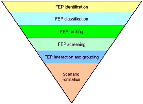
Fig. 6-9: Different stages in a FEP analysis, from identification to scenarioA plausible description of the future based on an internally consistent set of assumptions about key relationships and driving forces; note that scenarios are neither predictions nor forecasts formationA body of rock of considerable extent with distinctive characteristics that allow geologists to map, describe, and name it (Savage et al., 20042004 - D. Savage, P. R. Maul, S. Benbow and R. C. WalkeA generic FEP database for the assessment of long term performance and safety of the geological storage of CO2see more; Condor et al., 20112011 - J. Condor, D. Unatrakarn, M. Wilson and K. AsghariA Comparative Analysis of Risk Assessment Methodologies for the Geologic Storage of Carbon Dioxidesee more). |
Relational approaches with FEPs
There are a number of different ways in which the FEPs and their relationships can be developed to describe a site's behaviour. The retained FEPs are classified in both spatial and contextual terms (Savage et al., 2005; Korre and Durucan, 20092009 - A. Korre and S. DurucanA review of the international state of the art in risk assessment guidelines and proposed terminology for use in CO2 geological storagesee more). Three approaches have been used (CSLF, 20092009 - CSLFPhase I Final Report from CSLF Risk Assessment Task Forcesee more):
-
A "top-down" approach. An example of this approach is the Master Directed Diagram (mDD) approach, which was developed by Nirex of the UK (Nirex, 19981998 - L. Nirex, E. F. Bailey and D. E. BillingtonOverview of the FEP Analysis Approach to Model Developmentsee more). An MDD is a diagram like a tree-like structure(geology) Geological feature produced by the deformation of the Earth’s crust, such as a fold or a fault(geology) A surface at which strata are no longer continuous, but are found displaced; a feature within a rock such as a fractureAny break in rock along which no significant movement has occurred; or, more generally, the spatial arrangement of rocks that has some of the attributes of a network.
-
The Process Influence Diagram (PID) approach, which identifies and represents all possible influences between all FEPs within a system.
-
The interaction matrix approach. FEPs representing components of the system under consideration are placed on the leading diagonal elements (LDEs) of the matrix. Interactions between LDEs are then noted in the off-diagonal elements (ODEs).
Among these approaches, the PID has been used for the riskConcept that denotes the product of the probability of a hazard and the subsequent consequence of the associated event in the Weyburn CO2Carbon dioxide storage(CO2) A process for retaining captured CO2, so that it does not reach the atmosphere project (Stenhouse et al., 20052005 - M. J. Stenhouse, W. Zhou, D. Savage and S. BenbowFramework methodology for long-term assessment of the fate of CO2 in the Weyburn fieldsee more) and matrix representations of FEP interactions was applied to a hypothetical CO2Carbon dioxide storage(CO2) A process for retaining captured CO2, so that it does not reach the atmosphere project (Savage et al., 2005; Korre and Durucan, 20092009 - A. Korre and S. DurucanA review of the international state of the art in risk assessment guidelines and proposed terminology for use in CO2 geological storagesee more).
Regarding FEP methodology, there is some discussion as to whether a 'bottom-up' or 'top-down' approach is the best. 'Bottom-up' involves identifying every conceivable FEP and then building scenarios from these. This approach is time-consuming and might miss key scenarios through 'participant exhaustion' and time limitations. The 'bottom-up' approach uses the database directly to develop the assessment tools. 'Top-down' involves identifying a limited number of key riskConcept that denotes the product of the probability of a hazard and the subsequent consequence of the associated event scenarios. This approach might miss important FEPs, and important potential scenarios. In the 'top-down' approach, a FEP database can be used as an audit tool to ensure all relevant FEPs are included in the models, to document the reasons why others have not been considered (Condor at al., 2011) and to check completeness of the scenarios built. Overall, the 'top-down approach is favoured, but irrespective of the approach, it is important that the link between FEPs and scenarios is fully documented. An important issue connected with FEP/scenarioA plausible description of the future based on an internally consistent set of assumptions about key relationships and driving forces; note that scenarios are neither predictions nor forecasts riskConcept that denotes the product of the probability of a hazard and the subsequent consequence of the associated event analysis is that worst-case processes tend to be emphasised irrespective of how (un)likely they are to actually occur. Thus, leakage(in CO2 storage) The escape of injected fluid from the storage formation to the atmosphere or water column scenarios tend to get highlighted and qualifying uncertainties and assumptions ignored. Overall, quantitative assessment of the probability of any particular scenarioA plausible description of the future based on an internally consistent set of assumptions about key relationships and driving forces; note that scenarios are neither predictions nor forecasts occurring is very difficult, particularly for scenarios involving geological FEPs (e.g. fault(geology) A surface at which strata are no longer continuous, but are found displaced leakage(in CO2 storage) The escape of injected fluid from the storage formation to the atmosphere or water column, caprockRock of very low permeability that acts as an upper seal to prevent fluid flow out of a reservoir failure etc). An alternative to quantitative riskConcept that denotes the product of the probability of a hazard and the subsequent consequence of the associated event analysis may be to set out a storage(CO2) A process for retaining captured CO2, so that it does not reach the atmosphere plan, based on robust site characterisation, identify site-specific containmentRestriction of the movement of a fluid to a designated volume (e.g. reservoir) risks (and uncertainties), and design an efficient monitoringMeasurement and surveillance activities necessary for ensuring safe and reliable operation of a CGS project (storage integrity), and for estimating emission reductions and remediation strategy (Chadwick et al., 2008).
Steps after FEPs analysis
After FEPs analysis, detailed site characterization and simulation provide data to assess exposure due to the vulnerabilities in a qualitative or quantitative manner. Successful CO2Carbon dioxide geological storage(CO2) A process for retaining captured CO2, so that it does not reach the atmosphere requires thorough site characterization, especially for storage(CO2) A process for retaining captured CO2, so that it does not reach the atmosphere in saline formations that have not previously been considered an economic resource, as wellManmade hole drilled into the earth to produce liquids or gases, or to allow the injection of fluids as a clear understanding of the processes and mechanisms by which CO2Carbon dioxide is transported and trapped (NETL, 20112011 - NETLRisk Analysis and Simulation for Geologic Storage of CO2, Version 1.0see more). The estimated exposure indicates the probability that a particular negative event would occur. In the subsequent step, the effects of the vulnerabilities (impacts) are assessed using qualitative or quantitative tools. The impacts and exposure data from the previous two stages are used to assess the riskConcept that denotes the product of the probability of a hazard and the subsequent consequence of the associated event in the final step of the riskConcept that denotes the product of the probability of a hazard and the subsequent consequence of the associated event process, namely, riskConcept that denotes the product of the probability of a hazard and the subsequent consequence of the associated event characterization (Figure6. 4), through which the probability of the occurrence of events and the magnitude of loss from them are determined (effects assessment). In riskConcept that denotes the product of the probability of a hazard and the subsequent consequence of the associated event characterization, exposure and effects data are integrated to produce qualitative, semi-quantitative, or quantitative measures of riskConcept that denotes the product of the probability of a hazard and the subsequent consequence of the associated event. Ultimately, the set of quantitative and qualitative riskConcept that denotes the product of the probability of a hazard and the subsequent consequence of the associated event factors and their potential impacts become the basis for developing practical riskConcept that denotes the product of the probability of a hazard and the subsequent consequence of the associated event management and mitigationThe process of reducing the impact of any failure plans (NETL, 20112011 - NETLRisk Analysis and Simulation for Geologic Storage of CO2, Version 1.0see more).