MonitoringMeasurement and surveillance activities necessary for ensuring safe and reliable operation of a CGS project (storage integrity), and for estimating emission reductions of "Health, Safety and Environment (HSEHealth, safety and environment) risks" is focussed on the Earth's surface or the shallow subsurface. The probability of negative effects on protected subjects is highest where pathways could facilitate the ascent of fluids from the storage(CO2Carbon dioxide) A process for retaining captured CO2Carbon dioxide, so that it does not reach the atmosphereThe layer of gases surrounding the earth; the gases are mainly nitrogen (78%) and oxygen (around 21%) reservoirA subsurface body of rock with sufficient porosityMeasure for the amount of pore spaceSpace between rock or sediment grains that can contain fluids in a rock and permeabilityAbility to flow or transmit fluids through a porous solid such as rock to store and transmit fluids to the surface (Fig. 1-2). Such pathways have to be detected and mapped, and their properties have to be determined during site characterisation. This information provides input to site-specific riskConcept that denotes the product of the probability of a hazard and the subsequent consequence of the associated event assessments, which, in turn, provide fundamental data for setting up site-specific monitoringMeasurement and surveillance activities necessary for ensuring safe and reliable operation of a CGS project (storage integrity), and for estimating emission reductions plans that include monitoringMeasurement and surveillance activities necessary for ensuring safe and reliable operation of a CGS project (storage integrity), and for estimating emission reductions of these pathways.
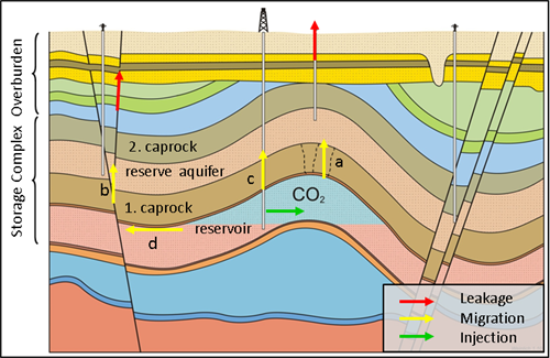 Fig. 1-2: Schematic representation of potential leakage(in CO2Carbon dioxide storage) The escape of injected fluid from the storage formationA body of rock of considerable extent with distinctive characteristics that allow geologists to map, describe, and name it to the atmosphereThe layer of gases surrounding the earth; the gases are mainly nitrogen (78%) and oxygen (around 21%) or water column pathways for CO2Carbon dioxide injected into saline formations (not to scale; slightly modified after v. Goerne et al., 20102010 - G. v. Goerne, F. Weinlich, F. MayAnforderungen und Vorschläge zur Erstellung von Leitfäden und Richtlinien für eine dauerhafte und sichere Speicherung von CO2 Stability-Abschlussberichtsee more). Fig. 1-2: Schematic representation of potential leakage(in CO2Carbon dioxide storage) The escape of injected fluid from the storage formationA body of rock of considerable extent with distinctive characteristics that allow geologists to map, describe, and name it to the atmosphereThe layer of gases surrounding the earth; the gases are mainly nitrogen (78%) and oxygen (around 21%) or water column pathways for CO2Carbon dioxide injected into saline formations (not to scale; slightly modified after v. Goerne et al., 20102010 - G. v. Goerne, F. Weinlich, F. MayAnforderungen und Vorschläge zur Erstellung von Leitfäden und Richtlinien für eine dauerhafte und sichere Speicherung von CO2 Stability-Abschlussberichtsee more). |
Potential leakage(in CO2 storage) The escape of injected fluid from the storage formation to the atmosphere or water column pathways may comprise:
Caprocks (a; Fig. 1-2): A central task of site characterisation is to demonstrate that thickness, strength, lateral distribution and sealing properties of caprocks facilitate safe and efficient storage(CO2) A process for retaining captured CO2, so that it does not reach the atmosphere of CO2Carbon dioxide. However, the presence of potentially weak spots of caprocks that could provide leakage(in CO2 storage) The escape of injected fluid from the storage formation to the atmosphere or water column pathways cannot be excluded. Indications for leakage(in CO2 storage) The escape of injected fluid from the storage formation to the atmosphere or water column through caprocks by such unknown pathways can be obtained by monitoringMeasurement and surveillance activities necessary for ensuring safe and reliable operation of a CGS project (storage integrity), and for estimating emission reductions secondary containmentRestriction of the movement of a fluid to a designated volume (e.g. reservoir) formations. The selection of suitable sites and parameters is critical for the early detection of such, potentially diffuse, leakage(in CO2 storage) The escape of injected fluid from the storage formation to the atmosphere or water column. For example in anticlinal structures, the largest pressure differences across a caprockRock of very low permeability that acts as an upper seal to prevent fluid flow out of a reservoir above a static gas column prevail at the top of a structure(geology) Geological feature produced by the deformation of the Earth’s crust, such as a fold or a fault; a feature within a rock such as a fracture; or, more generally, the spatial arrangement of rocks. Thus, this might be a strategic point for monitoringMeasurement and surveillance activities necessary for ensuring safe and reliable operation of a CGS project (storage integrity), and for estimating emission reductions caprockRock of very low permeability that acts as an upper seal to prevent fluid flow out of a reservoir integrity. The risks of undiscovered "gaps" in caprockRock of very low permeability that acts as an upper seal to prevent fluid flow out of a reservoir can be further minimised by monitoringMeasurement and surveillance activities necessary for ensuring safe and reliable operation of a CGS project (storage integrity), and for estimating emission reductions areas where general geological features indicate chances for pathways. Such indicators could be trends and variations of sedimentary facies or formationA body of rock of considerable extent with distinctive characteristics that allow geologists to map, describe, and name it thickness.
Faults (b; Fig. 1-2): Permeable faults in caprocks and in the overburdenRocks and sediments above any particular stratum of reservoirs may provide pathways for fluid ascent and hence imply potential HSEHealth, safety and environment risks. Older faults are often impermeable, sealed by mineralisationIs a natural form of geologically storing CO2 by the very slow reaction between CO2 and naturally occurring minerals, such as magnesium silicate, to form the corresponding mineral carbonate. Faults in neo-tectonic active regions may also provide barriers to fluid flow e.g. through fault(geology) A surface at which strata are no longer continuous, but are found displaced gouge or clay in unconsolidated sediments. Within the reservoirA subsurface body of rock with sufficient porosity and permeability to store and transmit fluids these faults may act as barriers to fluid flow and limit injectivityA measure of the rate at which a quantity of fluid can be injected into a well and reduce storage capacityThe accumulated mass of CO2 that can be stored environmentally safely, i.e., without causing leakage of CO2 or native reservoir fluids or triggering geologic activity that has a negative impact on human health or the environment and, thus, pose economical risks to storage(CO2) A process for retaining captured CO2, so that it does not reach the atmosphere operators.
Fault(geology) A surface at which strata are no longer continuous, but are found displaced zones often comprise networks of faults and fractures that are difficult to characterise in seismic images. Fault(geology) A surface at which strata are no longer continuous, but are found displaced properties vary along fault(geology) A surface at which strata are no longer continuous, but are found displaced planes. Hydraulic properties of faults can change due to pressures induced by CO2Carbon dioxide injectionThe process of using pressure to force fluids down wells. Closed faults become permeable, when pressures exceed the fault(geology) A surface at which strata are no longer continuous, but are found displaced strength (e.g. chiaramonte, 20082008 - Laura Chiaramonte, MarkD Zoback, Julio Friedmann, Vicki StampSeal integrity and feasibility of CO2 sequestration in the Teapot Dome EOR pilot: geomechanical site characterizationsee more). Geochemical reactions between fluids and adjacent rock or precipitation of minerals from ascending fluids may lead to self-sealing of faults or dissolution of carbonateNatural minerals (e.g. calcite, dolomite, siderite, limestone) composed of various anions bonded to a CO32- cation fractureAny break in rock along which no significant movement has occurred fillings. Therefore, detection and prediction of possible fluid pathways along faults is rather uncertain, so that faults need to receive special attention in monitoringMeasurement and surveillance activities necessary for ensuring safe and reliable operation of a CGS project (storage integrity), and for estimating emission reductions.
Boreholes (c; Fig. 1-2): Boreholes, especially from improperly installed and/or abandoned wells, may provide direct leakage(in CO2 storage) The escape of injected fluid from the storage formation to the atmosphere or water column pathways between reservoirs, groundwater, and the surface. Due to technical improvements in wellManmade hole drilled into the earth to produce liquids or gases, or to allow the injection of fluids cementation and logging, recently sealed boreholes are often considered safer than older, plugged ones, where less information on the wellManmade hole drilled into the earth to produce liquids or gases, or to allow the injection of fluids condition may be available. Thus, monitoringMeasurement and surveillance activities necessary for ensuring safe and reliable operation of a CGS project (storage integrity), and for estimating emission reductions of older, plugged wells has to be considered in monitoringMeasurement and surveillance activities necessary for ensuring safe and reliable operation of a CGS project (storage integrity), and for estimating emission reductions plans.
Spill points (d; Fig. 1-2) of structural traps are crucial areas for monitoringMeasurement and surveillance activities necessary for ensuring safe and reliable operation of a CGS project (storage integrity), and for estimating emission reductions the movement of a buoyant CO2 plumeDispersing volume of CO2-rich phase contained in target formation in saline aquifers. The actual expansion of a gas plume in a reservoirA subsurface body of rock with sufficient porosity and permeability to store and transmit fluids may be different from simplified reservoirA subsurface body of rock with sufficient porosity and permeability to store and transmit fluids simulations. In addition, spill points may be difficult to map in gently inclined structures. Spill points may be the starting points of leakage(in CO2 storage) The escape of injected fluid from the storage formation to the atmosphere or water column pathways. If a CO2 plumeDispersing volume of CO2-rich phase contained in target formation expands beyond spill points, it has to be carefully monitored. The ascent of fluids may follow a combination of several of the pathways described above in case of leakage(in CO2 storage) The escape of injected fluid from the storage formation to the atmosphere or water column. An illustrative example for such a complex leakage(in CO2 storage) The escape of injected fluid from the storage formation to the atmosphere or water column path is provided by the incident at the Bad Lauchstädt gas storage(CO2) A process for retaining captured CO2, so that it does not reach the atmosphere (Katzung et al., 19961996 - G Katzung, P Krull, F KühnDie Havarie der UGS-Sonde Lauchstädt 5 im Jahre 1988–Auswirkungen und geologische Bedingungensee more), where gas leaking from a cavern storage(CO2) A process for retaining captured CO2, so that it does not reach the atmosphere wellManmade hole drilled into the earth to produce liquids or gases, or to allow the injection of fluids at 110 m depth found its way via faults and secondary accumulations to the surface. Finally, gas burst to surface in several vents in a zone of 1.5 km length. Scenarios of such combined pathways have to be considered in riskConcept that denotes the product of the probability of a hazard and the subsequent consequence of the associated event assessments and for the positioning of monitoringMeasurement and surveillance activities necessary for ensuring safe and reliable operation of a CGS project (storage integrity), and for estimating emission reductions instruments.